
YXC75D Series
YXC75D Series
YXC75D Series Rated Capacitance Table
Code | Cap. pF | Tol. | Rated WVDC | Code | Cap. pF | Tol. | Rated WVDC | Code | Cap. pF | Tol. | Rated WVDC |
0R1 | 0.1 | A B C D | 250V | 2R4 | 2.4 | A B C D | 250V | 200 | 20 | F | 250V |
0R2 | 0.2 | 2R7 | 2.7 | 220 | 22 | ||||||
0R3 | 0.3 | 3R0 | 3.0 | 240 | 24 | ||||||
0R4 | 0.4 | 3R3 | 3.3 | 270 | 27 | ||||||
0R5 | 0.5 | 3R6 | 3.6 | 300 | 30 | ||||||
0R6 | 0.6 | 3R9 | 3.9 | 330 | 33 | ||||||
0R7 | 0.7 | 4R3 | 4.3 | 360 | 36 | ||||||
0R8 | 0.8 | 4R7 | 4.7 | 390 | 39 | ||||||
0R9 | 0.9 | 5R1 | 5.1 | 430 | 43 | ||||||
1R0 | 1.0 | 5R6 | 5.6 | 470 | 47 | ||||||
1R1 | 1.1 | 6R2 | 6.2 | 510 | 51 | ||||||
1R2 | 1.2 | 6R8 | 6.8 | B C J K | 560 | 56 | |||||
1R3 | 1.3 | 7R5 | 7.5 | 620 | 62 | ||||||
1R4 | 1.4 | 8R2 | 8.2 | 680 | 68 | ||||||
1R5 | 1.5 | 9R1 | 9.1 | 750 | 75 | ||||||
1R6 | 1.6 | 100 | 10 | F | 820 | 82 | |||||
1R7 | 1.7 | 110 | 11 | 910 | 91 | ||||||
1R8 | 1.8 | 120 | 12 | 101 | 100 | ||||||
1R9 | 1.9 | 130 | 13 | 121 | 120 | ||||||
2R0 | 2.0 | 150 | 15 | 151 | 150 | ||||||
2R1 | 2.1 | 160 | 16 | 181 | 180 | ||||||
2R2 | 2.2 | 180 | 18 | 201 | 200 |
Remark: special capacitance, tolerance and WVDC are available, consult with Yixin Microwave
Performance
Item | Specifications |
Quality Factors(Q) | 2000 min. |
Insulation Resistance(IR) | 105 Megohms min. @ +25°C at rated WVDC. 104 Megohms min. @ +125°C at rated WVDC. |
Rated Voltage(WVDC) | 250V |
Dielectric Withstanding Voltage (DWV) | 250% of rated Voltage for 5 seconds. |
Operating Temperature Range | -55℃ to +125℃ |
Temperature Coefficient(TC) | 0±30ppm/℃ |
Capacitance Drift | ±0.02% or ±0.02pF, whichever is greater. |
Piezoelectric Effects | None |
Environmental Tests
Item | Specifications | Method |
Terminal Adhesion | Temrination should not pull off, Cemera should remain undamaged | Linear pull force exerted on axial leads soldered to each terninal 2.0lbs |
Resistance to soldering heat | No mechanical damage Capacitance change:-1.0%~+2.0% Q>500 I.R.>10 G Ohms breakdown voltage:2.5 X WVDC | Preheat device to 150°C-180°C for 60sec DIP in 260°C±5°C solder for 10±1 sec.Measure after 24±2 hours cooling period |
Thermal Shock | No mechanical damage Capacitance change:±5% or 0.5pF max Q>500 I.R.>10 G ohms breakdown voltage:2.5 X WVDC | MIL-STD-202, Method 107, Condition A. At the maximum rated temperature(-55℃ and 125℃) stay 30 minutes.The time of removing shall be not more than 3 minutes. Perform the five cycles. |
Humidity (steady state) | No mechanical damage Capacitance change:±5% or 0.5pF max Q>300 I.R.>10 G ohms breakdown voltage:2.5 X WVDC | MIL-STD-202.Method 106 |
Low voltage hummidity | No mechanical damage Capacitance change:±3% or 0.3pF max Q>300 I.R.>10 G ohms breakdown voltage:2.5 X WVDC | MIL-STD-202, Method 103, Condition A, with 1.5 Volts D.C. applied while subjected to an environment of 85°C with 85% relative humidity for 240 hours min. |
Life | No mechanical damage Capacitance change:±2% or 0.5pF max Q>500 I.R.>10 G ohms breakdown voltage:2.5 X WVDC | MIL-STD-202, Method 108, for 1000 hours, at 125℃. 200% Rated voltage D.C. applied. |
YXC75D Chip Dimension
Item | length | width | thickness |
Chip Dimension | 0.080 (2.0) | 0.050(1.20) | 0.057(1.45) |
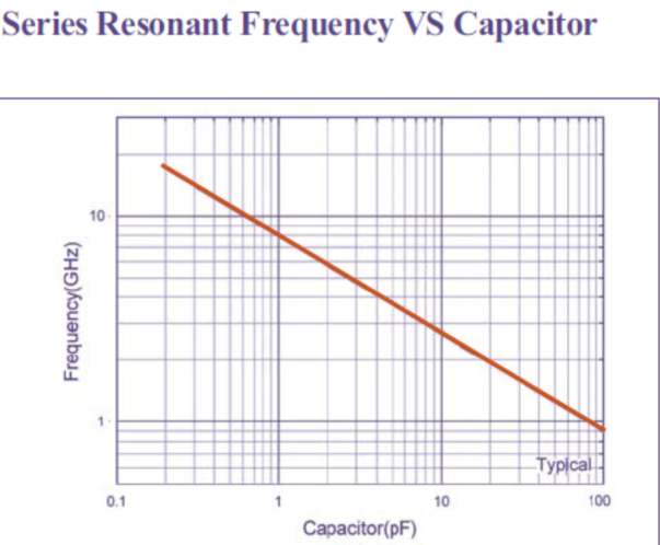
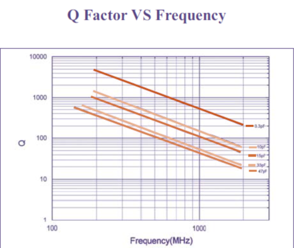
YXC75D Performance Curve
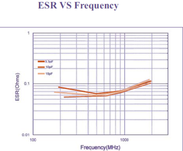
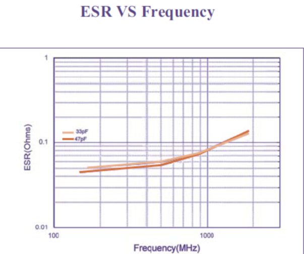
YXC75D Performance Curve